.jpg)

IFR DEPARTURES—RULES AND PROCEDURES
Departure Obstacle and Terrain Clearance
IFR departure procedures can be ground into two broad categories—procedures that are specified and procedures that are unspecified.
Unspecified Departure Procedures
Included in the category of airports with unspecified IFR departure procedures are departures from airports not listed in the Canada Air Pilot or the Jeppesen Airways Manual. It is quite legal to make an IFR departure from these so-called “VFR” airports,1 but there are no specified IFR departure procedures to follow. Conversely, there are also airports that appear in CAP/JEP with published instrument approach procedures, but which have not been assessed with respect to IFR departures—i.e., obstacle and terrain clearance required. The IFR departure procedure for these airports is published as “not assessed.” “Not assessed” airports are becoming more and more rare.2
Where IFR departure procedures are unspecified, it is the pilot’s sole responsibility to ensure terrain and obstacle clearance.
Specified Departure Procedures
Airports with specified IFR departure procedures,3 in contrast, are grouped on the basis of whether or not terrain and obstacles in the vicinity of the airport requires special restriction. Essentially, the airport is assessed as to whether or not terrain and obstacles meet what is described as the minimum climb gradient for IFR aircraft. The assumptions used to assess the minimum climb gradient are as follows:
After take-off, an IFR aircraft will
- cross the departure end of a runway by at least 35’;
- climb straight ahead to 400’ AAE prior to commending any turns; and
- maintain a climb gradient of at least 200’ per NM throughout the climb to a minimum IFR altitude for en route operations4.
In conjunction with the minimum climb gradient of 200’/NM, obstacles and terrain around the airport are assessed as to whether or not they penetrate specified slope or plane that is projected in all quadrants around the airport. The slope, which appears as an inverted cone, is based 35’ above the departure end of the runway, and subsequently extends upward at a rate of 152’ per 1 NM.5 If this slope is not penetrated by vicinity obstacles or terrain, Transport Canada will not publish special departure procedures in CAP, and the departure procedure is simply identified on the basis of the standard IFR visibility requirement—½ SM. By comparison, if this slope is penetrated, Transport Canada will publish specified IFR departure procedure designed to avoid the obstacles or terrain. The specified procedures are identified in CAP by the appearance of an asterisk—*—which refers the pilot to the text description of the procedure.
|
½ |
The departure procedure does not present any abnormal or unusual hazards. If the departing aircraft conforms to standard performance criteria, a departure can be conducted with ½ SM. The aircraft may safely turn in any direction after climbing straight-out to 400’ AAE, provided the minimum climb gradient of 200’/NM is maintained to vicinity MEAs. |
|---|---|
|
* |
The departure procedure does present potentially abnormal or unusual hazards. To ensure safe terrain and obstacle clearance for an IFR departure, specified procedures—indicated by the asterisk—must be adhered to. |
|
NOT ASSESSED |
As implied, the departure requirements for the airport have not been assessed. The pilot is solely responsible to ensure safe separation from terrain and obstacles |
Information pertaining to an airport’s IFR Departure Procedure is found on the Aerodrome Chart page, and in particular the box that appears in the lower left-hand corner marked Takeoff Minima.
Appearing in the Takeoff Minima box, the published IFR Departure Procedure will therefore take one of three forms, summarised above.
Unrestricted IFR Departures (½)
The “½” depiction means “takeoff, climb on course” for the specified runway or runways. This is the case, for example, with respect to an IFR departure from any of the runways that appear at Fort St. John Airport—see the Takeoff Minima box in the lower left-hand corner. It is implied, therefore, that the terrain surrounding Fort St. John Airport presents less terrain and obstacle hazards then, for example, an IFR departure from an airport located in a mountainous area. Specifically, based on the ½ depiction that is published for Fort St. John, we can assume that no obstacles penetrate the reference slope or plane extending upward in all quadrants at a rate of 152’ per nautical mile. The bottom of this “inverted cone” is based 35’ above the departure end of the runway. Since all of the runways are rated as simply “½” we know that this clearance requirement is met for all for runway departure ends that appear at this airport.
Restricted IFR Departures (*)
The appearance of the asterisk for a specified runway implies that reference must be made to required published procedures to ensure obstacle and terrain clearance, which may include specified climb gradients, routings, and/or visual climb requirements.6 An example of this is the specified departure procedures for Prince George.7
Examining the departure procedures you will note two types. First there are those runways where the minimum ½ SM visibility is specified, but for which prescribed routing must be followed—this is the case, for example, with respect to the departures from Rwys 15, 33, and 06. In contrast, the departure from Rwy 24 requires not ½ SM, but specified visibility—SPEC VIS— to a specified altitude—in this case, 2700’ ASL. In the case of the ½ SM departures, only visibility governs, and cloud ceiling has nothing to do with it. In the case of the SPEC VIS departure from Rwy 24, however, both visibility and cloud ceiling govern.
In the case of ceiling that is required, this of course will vary with each specified departure. In the case of visibility, however, we must return to the prescribed aircraft category based on manoeuvring speed:
Remember that the manoeuvring speed specified here does not relate to Va, but instead relates in this case to the planned speed the pilot will manoeuvre the aircraft during the departure phase of flight. Based on the speed category, the Specified Takeoff Minimum Visibility (SPEC VIS) is prescribed as follows:
Accordingly, an IFR departure off Rwy 24 requires in the case of Category B aircraft—aircraft with a departure manoeuvring speed of between 91 and 120 KTS—a reported surface visibility of 1½ SM. In contrast, Rwys 15 and 33 are less restrictive to IFR departures, requiring only ½ SM. Note that IFR departures are not mentioned with respect to Rwys 19, 01, and 06. Departures off these runways will not be authorised for IFR aircraft; instead, the aircraft would have to depart VFR with the intention of activating an IFR clearance once in the air.
The Prince George departure procedures are somewhat unusual as normally the appearance of a SPEC VIS component is provided as an alternative to ½ SM departures with higher than normal climb gradient. Thus, aircraft that cannot meet the required higher climb gradient or gradients can choose the SPEC VIS alternative. It is important to remember, however, the minimum IFR climb gradient of 200’/NM still apply to SPEC VIS departures after cloud has been entered (the prescribed altitude to which a visual climb is specified).
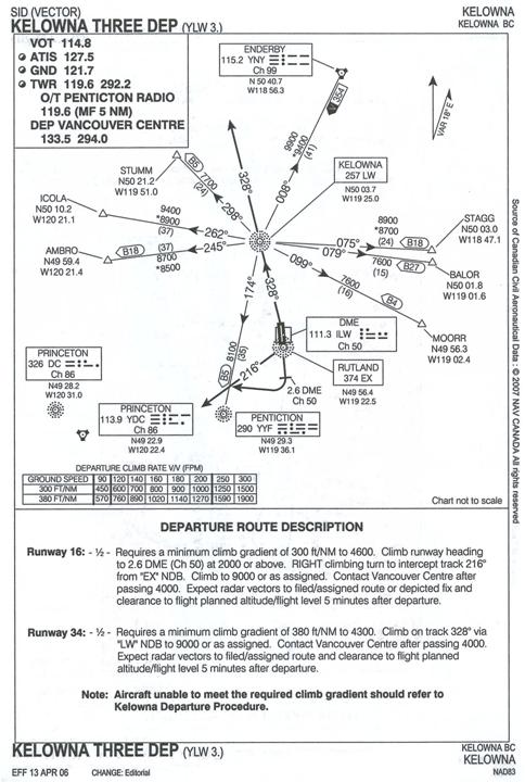
More commonly, the SPEC VIS departures are provided as an alternative to the ½ SM departures that have higher than normal climb gradients. This is the case, for example, with the departures that are published for Cranbrook Airport, as depicted below.
All of the departure options from Cranbrook have specified routings, owing to the imposing height of surrounding terrain. Pilots are nevertheless given two options.
The first option to take the ½ SM departures. Careful consideration must be given to the climb gradient capabilities of the aircraft and whether those published can be sustained to the en route MEAs. A Category A or B aircraft requires only 270’ per NM climb to depart off Runway 16, but to depart off Runway 34 will require a more demanding 420’/NM. The advantage of these departures is that consideration must only be given to visibility, which is the governing factor—only ½ SM ground visibility on departure is required, irrespective of the ceiling. The disadvantage of these departures pertains to whether or not the required climb gradients can be sustained—in a light twin, for example, it is quite likely that the failure of an engine will quickly render the aircraft unable to comply.8
Accordingly, careful consideration must be given to the ability of the aircraft to meet or exceed the increased climb gradients. To do this, the climb gradient chart that appears in CAP GEN must be consulted. This graph, depicted below,9 enables the conversion of a “feet per nautical mile” value to a “feet per minute” value, based on the anticipated groundspeed during the departure phase. Be sure not to mix up the scales posted on either side of the graph. Note also that a multi-engine pilot should plug in the published single-engine climb performance valued (assuming one of the engines has failed). The example shown demonstrates the application of the Cranbrook climb gradient required for the ½ SM departure off Runway 16; the climb groundspeed is assumed to be 120 KTS. For some airports, the climb rates, based on the specified climb gradients, are set out in table form on the CAP plates; these are always provided in JEP plates.
In the case of the SPEC VIS procedure for Cranbrook Airport, climb gradient is of course not specified in the text description. Don’t let this create any confusion, however, as the assumed minimum climb gradient of 200’/NM still applies. This requirement, however, only kicks in after the aircraft has climbed visually over the airport to the specified altitude—in the case of Cranbrook, 4400’ ASL. Thus, ceiling limitations govern SPEC VIS departures. When evaluating the latest METAR sequence, be sure you properly convert the SPEC VIS altitude—published in height above sea level—to the METAR ceiling values—height above ground. To conduct the SPEC VIS departure from Cranbrook, then, the minimum ceiling requirement that must appear in the METAR is 4400’ minus the elevation of the airport—3082’ (as published in the Canada Flight Supplement). So the ceiling must be 1400’ or higher.
In the absence of a published visibility, the pilot may depart using a takeoff visibility that will allow obstacle and terrain clearance, but in no case should the takeoff visibility be less than ½ SM.
Additionally, where aircraft or other limitations preclude a pilot from conforming to published procedures, the pilot is again responsible for determining alternative safe departure procedures.
General Departure Requirements
Initial Contact
On initial contact with ATC a departing IFR pilot should state the destination and planned initial cruising altitude.
|
Pilot: |
“Langley Ground, this is Seneca ABC at Hangar 17 with information Alpha. IFR Victoria, 4000.” |
|
ATC: |
“ABC, Roger . . .” |
|
Pilot: |
“Victoria Clearance Delivery, this is Seneca ABC on Ramp 3 with information Alpha. IFR Langley, 4000.” |
|
ATC: |
“ABC, Victoria Clearance, Roger . . .” |
IFR Clearances
Where a Clearance Delivery frequency is published, the pilot shall obtain the IFR clearance on this frequency prior to contacting ground control.
Where Clearance Delivery does not exist, the ground controller will provide the IFR clearance after a taxi authorisation is issued.
For turbojet aircraft with high fuel consumption rates, IFR clearances may be obtained prior to engine start with the phrase “Ready to start now . .” or “Ready to start at (time) . .” and such requests should be made within 5 minutes of actual engine start.
Standard Instrument Departures (SIDs)
A SID is a planned IFR air traffic control departure procedure published in CAP/JEP. It contains both a descriptive text as well as a graphic depiction. They are designed to provide an instrument flight transition from the terminal environment to the en route structure.
There are two types of SIDs, the first being a Pilot Navigation SID whereby the pilot is required to use the chart as reference for navigation, and the second is the Vectored SID in which ATC provides radar navigation guidance to routes or fixes depicted on IFR charts.
Pilots are not required to accept a SID clearance and the pilot should request a detailed clearance should doubt exist concerning the SID requirements.
There are two segments associated with a SID, the first or initial segment is from the departure end of the runway and lasts until the aircraft first turns from the initial departure heading, and the second segment begins lasts from the first turning point to the SID termination point.
If an IFR pilot is instructed to fly “runway heading” or if a SID does not specify a heading for the first segment, the pilot is expected to maintain a heading that corresponds with the extended centre line of the departure runway. Drift corrections are not applied.
Where a SID contains a specific published heading, the heading must of course be maintained until vectoring begins.
When a SID clearance is issued, the clearance includes the name of the SID, the SID termination fix (if appropriate), the transition (if necessary) and, also if necessary, the time or location at which the pilot may expect to climb to an suitable altitude (this may be conveyed by way of “expect further clearance”).
ATC may amend elements of a SID—for example the initial heading or altitude—but this amendment does not cancel the SID.
If ATC assigns an altitude that is not operationally suitable, and if the pilot has not been informed when a clearance to another altitude may be expected, it is the responsibility of the pilot to advise ATC of the unsatisfactory altitude assignment. The pilot, in evaluating an altitude assignment, must ensure the altitude will permit flight to the destination airport should a communications failure occur.
SIDs may specify communication failure procedures, and such procedures supersede standard communication failure procedures.
SIDs will conform to any noise abatement procedures governing departures, and radar vectors will only begin once noise abatement procedures are completed.
It is important to note that ATC expressions such as “on departure, right turn climb on course” or “on departure, left turn on course” are not to be regarded as specific departure instructions, and it remains the pilot’s responsibility to ensure terrain and obstacle clearance is achieved by first conforming with the IFR departure procedure.
While civilian SIDs incorporate obstacle and terrain clearance, this is not the case with textual form of SIDs published for military aerodromes.
Release from Tower Frequency
If an IFR departure is made within a terminal control area, the pilot will be cleared by the tower to contact a specific control unit on a specified frequency once the aircraft is clear of conflicting traffic.
Where the pilot is advised prior to takeoff to change to a specific departure frequency, this change should be done as soon as practicable after takeoff.
If the departure airport is not located in a terminal control area, the pilot, when requesting a release from frequency, should advise the tower of the frequency or agency the pilot intends to change to.
The initial call to a departure controller should contain at least the following:
|
Pilot: |
“Victoria Terminal. ABC climbing off Runway 19 Langley. Through 1600’ for 2000’.” |
|
ATC: |
“ABC, roger. Squawk Ident.” |
|
ATC: |
“ABC is radar identified through 1800’. Maintain 4000’.” |
- the aircraft call sign;
- the runway of departure;
- the present altitude vacating (to the nearest 100’ increment)10; and
- the assigned altitude (including the altitude contained in a SID if applicable).
Noise Abatement
Nothing in a noise abatement procedure shall prevent a pilot from exercising authority for safe operations. The one exception is the climb gradient which, if published, must be maintained or an alternative procedure adopted.
Noise abatement will not be a factor in determining the departure runway when the runway is not dry and clear, the crosswind exceeds 25 KT, or the tailwind does not exceed 5 KT.
Airports with a departure procedure published in CAP/JEP are said to have an IFR Departure Procedure.
IFR Departures from Uncontrolled Airports
If an IFR departure is planned from an uncontrolled airport, the pilot shall
- obtain an ATC clearance if in controlled airspace;
- report intentions and departure procedures prior to moving on to the runway or before aligning the aircraft on the takeoff path; and
- determine by radio and visual observation that no other aircraft or vehicle will present a conflict during takeoff.
Additionally, the pilot shall maintain a listening watch during takeoff from an uncontrolled airport and after takeoff from an uncontrolled airport where an MF has been designated (and maintain the listening watch until the aircraft has departed from the specified distance and/or altitude associated with an MF).
As soon as possible after leaving the specified distance and/or altitude associated with the MF, the pilot shall communicate with the appropriate ATC unit or a ground unit on the en route frequency.
Special Note: If an aircraft does not commence a departure within 60 minutes of the proposed departure time specified in an IFR flight plan, Search and Rescue will be activated.
References:
1 The only legal restriction is that an IFR aircraft cannot enter controlled airspace without an ATC clearance.
2 The only “not-assessed” airport in the British Columbia CAP is Comox Airport, and this is only because public access to Comox is restricted.
3 By definition, such airport would have to appear in CAP.
4 The minimum IFR altitude for en route operations refers to the airway structure and airway MEAs.
5 The information that appears in the Instrument Procedures Manual is unfortunately scanty—see Section 4.2.6 Take-Off Criteria and Minima.
6 To suggest that the asterisk is used only for terrain and obstacle clearance purposes is somewhat misleading. The asterisk—and the specified departure procedures that it references—can be used to route IFR aircraft around Class F airspace, or it can be used to integrate departing IFR aircraft with overlying ATC airspace and routing structures. In the case of Langley Airport, for example, the specified routing to the Whatcom VORTAC after departure reduces conflict with the final approach courses for Vancouver Airport, and keeps Langley departures out of surrounding Class F airspace.
7 The Aerodrome Chart presented here has since been modified to be incorporated into a SID. This older format nevertheless conveys the general format of specified IFR departures.
8 Faced with an engine failure of an engine in a light twin out of Cranbrook, the pilot of an aircraft unable to meet the departure climb gradient would have to convert to published approach procedures in an attempt to land the aircraft. With this scenario, you can see the important of only conducting a departure if the weather at the departure airport is above or at the approach minima. With a departure in weather below approach minima, an aircraft cannot safely return in the event of an emergency. For this reason, the regulations governing commercial operations prohibit the departure of an aircraft that cannot sustain adequate single-engine climb performance from departing IFR when weather is below approach minima, irrespective of departure minima.
9 The positioning of the lines on this graph are not accurate and this should not be used for calculation purposes.
10 ATC must verify the accuracy of the Mode C altitude readout. The Mode C altitude readout is valid if it does not exceed the reported value by 200’. The readout is considered invalid if it exceeds the reported value by 300’ or more.